Welcome to the world of electrical conductors, where the circular mils table NEC 2020 reigns supreme as the go-to resource for determining the cross-sectional area of conductors. This indispensable tool empowers electrical professionals to make informed decisions about conductor selection, ensuring safety and efficiency in electrical installations.
In this comprehensive guide, we will delve into the intricacies of the circular mils table, exploring its structure, applications, variations, and limitations. With real-world examples and practical insights, we aim to equip you with the knowledge and confidence to navigate the complexities of electrical conductor sizing.
Introduction
In electrical applications, the cross-sectional area of a conductor is a crucial factor that determines its current-carrying capacity and resistance. Circular mils (CM) is a unit used to measure the cross-sectional area of round conductors, such as wires and cables.
The National Electrical Code (NEC) 2020 includes a circular mils table that provides a convenient reference for determining the cross-sectional area of conductors based on their diameter in inches or millimeters. This table is essential for electrical professionals to ensure that conductors are properly sized for the intended electrical load, ensuring safety and efficient operation of electrical systems.
Significance of Circular Mils, Circular mils table nec 2020
The cross-sectional area of a conductor directly influences its ability to carry current. A larger cross-sectional area allows for greater current flow, while a smaller cross-sectional area limits the current capacity. Circular mils is used to quantify this cross-sectional area, providing a precise and standardized unit of measurement.
Purpose of Circular Mils Table in NEC 2020
The circular mils table in the NEC 2020 serves as a comprehensive reference for electrical professionals. It enables them to quickly determine the cross-sectional area of round conductors based on their diameter, eliminating the need for complex calculations. This table is particularly useful for selecting appropriate conductors for electrical installations, ensuring compliance with code requirements and safe operation of electrical systems.
Understanding the Circular Mils Table
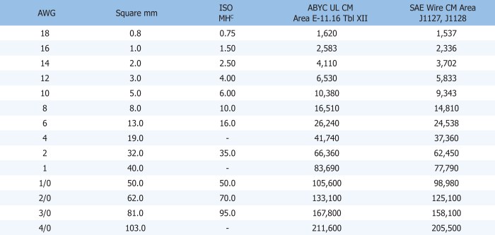
The Circular Mils Table, found in Chapter 9 of the NEC 2020, is an essential resource for electrical professionals. It provides the cross-sectional area of conductors in circular mils, which is a unit of measurement for the area of a circle.
The table is organized by conductor size, with the smallest size at the top and the largest size at the bottom. Each row in the table includes the conductor size, the cross-sectional area in circular mils, and the resistance in ohms per 1,000 feet.To
use the table, simply find the conductor size you are interested in and read across the row to find the cross-sectional area. For example, if you are using a 10 AWG conductor, the cross-sectional area is 10,380 circular mils.
The circular mils table in NEC 2020 provides valuable information for electrical design. It helps determine the appropriate wire size based on current capacity and voltage drop. When working with electrical systems, it’s crucial to have reference materials nearby, such as books on electrical theory and design . By keeping these resources within reach, you can quickly access the information you need to ensure the safety and efficiency of your electrical installations.
The circular mils table in NEC 2020 is an essential tool for any electrician or electrical engineer.
Conductor Resistance
The Circular Mils Table also includes the resistance of conductors in ohms per 1,000 feet. This information can be used to calculate the voltage drop in a circuit. To calculate the voltage drop, simply multiply the resistance of the conductor by the length of the circuit in feet and then by the current in amps.
For example, if you are using a 10 AWG conductor that is 100 feet long and carrying 10 amps, the voltage drop would be 0.1038 volts.The Circular Mils Table is a valuable resource for electrical professionals. It can be used to determine the cross-sectional area and resistance of conductors, which is essential for designing and installing electrical systems.
Applications of the Circular Mils Table
The circular mils table finds extensive applications in electrical installations, primarily for determining the appropriate conductor size for specific electrical requirements. It plays a crucial role in ensuring the safe and efficient operation of electrical systems.
Calculating Ampacity and Voltage Drop
The circular mils table is instrumental in calculating the ampacity, or current-carrying capacity, of a conductor. Ampacity is a critical factor in preventing overheating and potential electrical hazards. The table provides the relationship between the conductor’s circular mils area and its ampacity for various materials, such as copper and aluminum.
Additionally, the circular mils table aids in calculating voltage drop, which refers to the reduction in voltage along a conductor due to its resistance. By knowing the conductor’s resistance per 1000 feet, obtained from the table, engineers can determine the voltage drop for a given length and load.
Selecting Appropriate Conductors
The circular mils table serves as a valuable tool for selecting the appropriate conductor size for electrical installations. By considering factors such as the required ampacity, voltage drop, and type of installation, engineers can use the table to determine the optimal conductor size that meets the specific electrical demands.
Proper conductor selection is crucial for ensuring the safe and efficient operation of electrical systems. The circular mils table provides a comprehensive reference for selecting conductors that can handle the required current and minimize voltage drop, ensuring reliable and efficient power distribution.
Variations in the Circular Mils Table
The NEC 2020 circular mils table has undergone several variations and updates compared to previous editions. These changes were primarily driven by the need to align with the latest industry standards and technological advancements.
One significant change is the addition of new wire sizes to the table. This was done to accommodate the increasing use of smaller wire gauges in electrical applications. The new wire sizes include 18 AWG, 16 AWG, and 14 AWG.
Another notable change is the revision of the ampacity values for certain wire sizes. These revisions were made to reflect the latest research on the current-carrying capacity of conductors. In general, the ampacity values have been increased for most wire sizes, allowing for higher current flow.
These variations in the circular mils table have important implications for electrical contractors and designers. It is crucial to stay up-to-date with the latest changes to ensure the safety and efficiency of electrical installations.
Implications of the Changes
- The addition of new wire sizes provides more options for electrical contractors and designers, allowing them to select the most appropriate wire size for their specific applications.
- The revised ampacity values allow for higher current flow, which can be beneficial in applications where space is limited or where high-power equipment is used.
- Staying up-to-date with the latest changes in the circular mils table is essential for ensuring the safety and compliance of electrical installations.
Practical Examples: Circular Mils Table Nec 2020
The circular mils table finds numerous applications in electrical engineering, particularly in determining the appropriate wire size for a given current and voltage.
Here are some examples demonstrating the practical use of the circular mils table:
Example 1: Selecting Wire Size for a Motor
Suppose we need to determine the appropriate wire size for a 10 horsepower (HP) motor that operates at 240 volts. The motor’s nameplate indicates a full-load current of 28 amperes.
Using the circular mils table, we find that a wire size of 12 AWG (American Wire Gauge) has a circular mil area of 6530 cmils. According to the National Electrical Code (NEC), the minimum circular mil area for a 28-ampere circuit at 240 volts is 5500 cmils.
Therefore, a 12 AWG wire with a circular mil area of 6530 cmils is suitable for this application.
Example 2: Calculating Voltage Drop in a Circuit
Consider a circuit with a total load of 10 kilowatts (kW) operating at 120 volts. The circuit length is 100 feet, and the wire size is 10 AWG.
Using the circular mils table, we find that 10 AWG wire has a circular mil area of 10380 cmils. The resistance per 1000 feet for 10 AWG wire is 1.029 ohms.
The voltage drop in the circuit can be calculated using the following formula:
Voltage drop = (Circuit length in feet)
- (Load current in amperes)
- (Resistance per 1000 feet)
In this case, the load current is:
Load current = Load power (kW) / Voltage (V) = 10 kW / 120 V = 83.33 amperes
Therefore, the voltage drop is:
Voltage drop = 100 feet
- 83.33 amperes
- 1.029 ohms = 86.04 volts
This means that there will be an 86.04-volt drop in the circuit, which may need to be considered in the design and operation of the circuit.
Advanced Applications
Beyond its fundamental use in electrical design, the circular mils table finds applications in specialized fields, including the design of electrical transformers and motors.
In transformer design, the circular mils table helps determine the cross-sectional area of the conductor required to carry the current safely and efficiently. By selecting the appropriate circular mil value, engineers can optimize the transformer’s performance, minimizing losses and ensuring reliable operation.
Motor Design
Similarly, in motor design, the circular mils table is used to determine the conductor size for the stator and rotor windings. The appropriate circular mil value ensures that the motor can deliver the required power while maintaining efficiency and minimizing overheating.
Considerations and Limitations
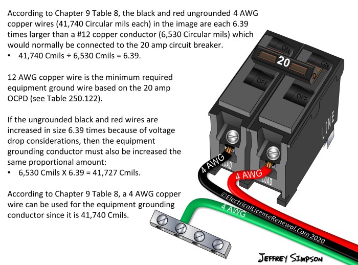
The circular mils table is an essential tool for electrical engineers and contractors, but it’s crucial to understand its limitations and considerations for accurate and safe applications.
It’s important to note that the table provides approximate values, and the actual current-carrying capacity of a conductor may vary depending on factors such as temperature, insulation type, and installation conditions. Therefore, it’s essential to consult the National Electrical Code (NEC) and other applicable electrical codes and standards for specific requirements and guidelines.
Factors Affecting Current-Carrying Capacity
- Temperature:Higher temperatures can reduce the current-carrying capacity of a conductor.
- Insulation Type:Different types of insulation have varying degrees of resistance to heat and can affect the current-carrying capacity.
- Installation Conditions:Factors such as conduit size, spacing between conductors, and ambient temperature can influence the current-carrying capacity.
Question & Answer Hub
What is the circular mils table?
The circular mils table is a reference table that provides the cross-sectional area of electrical conductors in circular mils (CM).
How do I use the circular mils table?
To use the circular mils table, simply locate the conductor size (AWG or kcmil) in the left-hand column and read the corresponding cross-sectional area in CM in the right-hand column.
What is the difference between AWG and kcmil?
AWG (American Wire Gauge) and kcmil (thousand circular mils) are two different units of measurement for conductor size. AWG is used for smaller conductors, while kcmil is used for larger conductors.